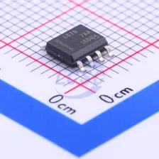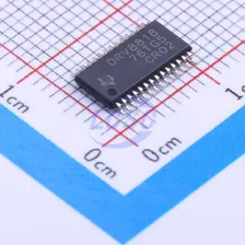

ZH6551EC
3V~28V TSSOP-16 Motor Drivers, Controllers
- Manufacturer
- Semiment
- Manufacturer part #
- ZH6551EC
- Store part #
- C54123386
- Package / case
- TSSOP-16
- Category
- Motor Drivers, Controllers
- Packaging
- Tape & Reel (TR)
Every Order Guarantee
100% Authentic · 30-Day Return or Replacement · policy
3,965 in stock
#C54123386
Stock & price checked 6 days ago
| Quantity | Unit price | Pack price |
|---|---|---|
| 5+ | ₹42.16 | ₹210.80 |
| 50+ | ₹33.34 | ₹1,667.00 |
| 150+ | ₹29.56 | ₹4,434.00 |
| 500+ | ₹24.83 | ₹12,415.00 |
| 3,000+ | ₹22.73 | ₹68,190.00 |
| 6,000+ | ₹21.46 | ₹1,28,760.00 |
5 × ₹42.16
₹210.80
excl. GST
₹248.74 incl. 18% GST
- Dispatch in 7–10 working days
- GST invoice with every order
- Standard pack: 3,000 per reel
ZH6551EC
₹210.80 for 5 + GST
Specifications
- Drive Type
- Single Phase
- Features
- Motor stall protection;Motor speed indication
- Technology
- No
- Voltage - Supply
- 3V~28V
- Interface
- PWM
- Operating Temperature
- -40℃~+125℃
- Output Current
- 800mA
- Number of Half Bridges
- 2
Packaging & compliance
- RoHS
- RoHS
- Lifecycle
- Active
- Packaging
- Tape & Reel (TR)
- Standard pack
- 3,000 / Reel
- Sold per
- Piece
- Minimum order
- 5 (multiples of 5)
- Unit weight
- 1 g
Overview
ZH6551 is a single-phase brushless DC motor driver IC with a built-in Hall sensor, H-bridge pre-driver, soft commutation and soft-start control, and protection features including current limiting, short circuit, overvoltage, overtemperature, and undervoltage. The IC supports PWM speed control (with optional closed-loop speed mode), configurable speed curves, and FG output feedback. Users can select the built-in Hall sensor or an external switch-type Hall sensor with input from the HALL pin. Use V5 to power the Hall sensor. ZH6551 features a sleep mode; after PWM = 0, the sleep current is less than 10uA. The PWM input signal frequency range is 50Hz~100KHz; the IC reads the PWM input duty cycle for speed control. The FG output uses open-drain output to feed back the current speed — one electrical cycle corresponds to one FG output cycle. The output waveform of ZH6521 can be configured via 7 parameters. The Slope satisfies the equation: (Slope_n + 1) / 32 = tan(θ_n). The first inflection point is 0°, requiring no configuration. The first-segment slope1 is proportional to tan(θ), with a maximum of 45° (corresponding to slope1 = 31), meaning the amplitude takes 45° electrical angle to rise from 0 to 100%. The configurable angle range is 0° to 45° with 32 steps. The second inflection point is Turning-point2, ranging from 0° to 90°. The second-segment slope2 is proportional to tan(θ2), with a maximum of 45° (corresponding to slope2 = 31); a larger configured value yields a steeper rising slope. The third inflection point is Tuning-point3, ranging from 90° to 180°. The third-segment slope3 is a falling slope; a larger configured value yields a steeper falling slope. The fourth inflection point is Tuning-point4, ranging from 90° to 180°. The fourth-segment slope4 is a falling slope, proportional to tan(θ4), configured in the same manner as slope1. After the fourth segment drops to zero, the voltage is set to zero until commutation occurs. The speed curve is configured using 10 registers (16-bit each). The low 8 bits of each register store the duty cycle, and the high 8 bits store the target speed (as a ratio of the maximum target speed). Users write up to 10 data pairs into the table; each pair represents the X-coordinate (duty cycle) and Y-coordinate (target speed) of an inflection point, and the speed curve is determined by these 10 data points. External PWM duty cycle adjustments do not take effect immediately at the output. Instead, an internal PWM ramp controller governs the actual output voltage according to the ramp value, enabling smooth start and smooth stop functions. The step time of the rising ramp is set by acc_time_set, and the step time of the falling ramp is set by dec_time_set. When PWM is set to 1, the motor speed increases gradually; the soft-start time can be configured via register bits. When PWM is set to 0, the motor speed decreases gradually; the soft-stop time can be configured via register bits. The windmill start strategy reduces the motor speed to the configured minimum speed before starting the motor, preventing the motor from being started at high speed. This avoids the motor's back-EMF energy feeding back into the power supply, which could cause the supply voltage to spike excessively and reduce high-voltage stress on voltage-rated components. If the speed is too high, the motor can be braked or coasted down to the minimum speed; the minimum speed is set via the speed_low_set register. If the speed is already below the minimum speed, the motor starts directly. ZH6521 reserves 32 bits for storing customer product and version information, stored at memory addresses EP14–EP15.
Applications
- Single-phase BLDC fan
- Single-phase BLDC water pump
Key features
- Single-phase fan driver with selectable internal or external Hall sensor
- 3V~28V supply voltage with integrated PNmos pre-driver
- Low-current standby mode <10uA
- Configurable advance angle for efficiency optimization
- Configurable speed profile
- Configurable output waveform
- Optional closed-loop speed control
- Optional FG/RD diagnostic output
- PWM input frequency 50Hz to 100kHz
- Current limiting function
- Short-circuit, over-temperature, over-voltage, and under-voltage protection
Same category